G-code vs STL: which file do you need for a printing video?
Choose STL for model-based visuals or G-code for actual extrusion paths, and learn what each file can and cannot prove about a 3D print.
Written by
3D Print Timelapse Team
The 3D Print Timelapse team writes practical guides about 3D printing files, timelapse workflows, and clearly labeled rendered print animations.
Use an STL when you want to begin with the shape of a model. Use text G-code when you want a video to follow the extrusion paths produced by a slicer. The choice is not mainly about which extension is newer or more detailed. It is about whether the video should present the designed object or the planned printing motion.
That distinction matters because an STL and a G-code file represent different stages of the same workflow. An STL is commonly an input to slicing. G-code is commonly an output from slicing. Neither is automatically the better source for every printing video.
The short comparison
| Question | STL | Text G-code |
|---|---|---|
| What does it describe? | A surface made from triangles | Commands and coordinates prepared for a printer |
| Does it contain the slicer's toolpath? | No | Usually, when it is slicer output |
| Does it reliably contain model color? | No | Not as a rendered surface material |
| Is it tied to print settings? | No | Usually, when produced by a slicer |
| Best fit for video | A clean model-based layer reveal | A path-based view of extrusion order |
| Can you send it straight to a printer? | No, it must be sliced first | Only after confirming it matches the printer, material, and setup |
A same-source comparison
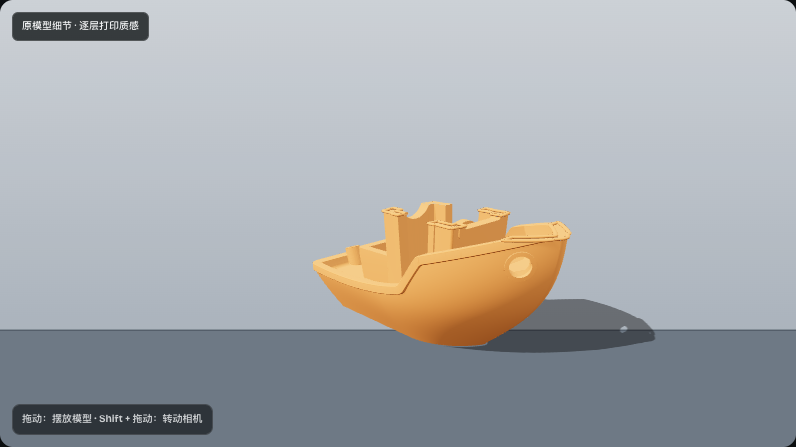
For the screenshots below, we started with the official CC0 3DBenchy STL and used two separate workflows. The model view reads the STL geometry directly. The path view reads plain text G-code sliced from that same STL with PrusaSlicer 2.9.4 at 0.20 mm layer height, 15 percent infill, and no generated supports. 3D Print Timelapse parsed that file as 240 layers and 84,050 extrusion segments. That segment count describes this viewer's parse of this file, not a universal property of the model.
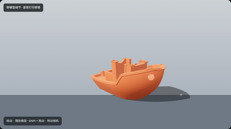
The STL view keeps the source surface and applies one preview color. It does not show the slicer's perimeter, infill, or travel decisions.
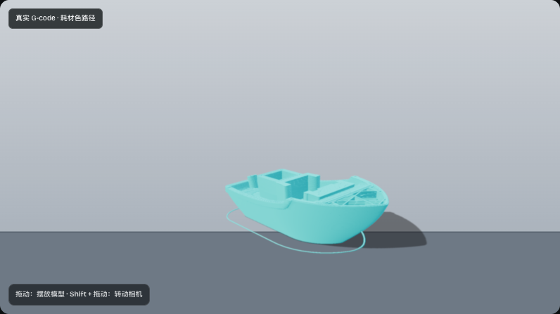
The G-code view follows the extrusion moves the parser recognizes. The visible skirt, walls, and internal lines come from the slice, while machine behavior such as homing offsets and calibration remains outside the preview.
What an STL gives a video tool
An STL describes a triangulated surface. Each facet records three vertices and a normal, in either an ASCII or binary representation. The Library of Congress format description for STL notes two limitations that are important here: the format does not provide a standard way to declare measurement units, and color conventions used by some binary files are not interoperable.
In practical terms, an STL is useful when the silhouette and surface are the main subject. A renderer can position the mesh, light it, choose a display color, and reveal it in horizontal layers. That can produce a clear explanation or product shot without claiming to reproduce every nozzle move.
An STL alone cannot answer questions such as:
- What layer height was selected?
- How many perimeters will be printed?
- Which infill pattern and density will be used?
- Where will the printer travel without extruding?
- Which temperature, speed, or retraction settings apply?
- Will a slicer generate supports, a brim, or a raft?
The missing unit declaration deserves special attention. A vertex value of 20 has no inherent millimeter or inch label in an STL. 3D Print Timelapse reads STL dimensions as millimeters, so check the displayed size before trusting the composition. A model exported in inches but interpreted as millimeters can appear far too small.
STL also has no dependable portable material system. If you need the source model's colors or textures in a visual reveal, an embedded-resource GLB is a better fit. The differences are covered in STL vs GLB vs 3MF: Geometry, Color, and Printing Data.
What G-code gives a printing video
For fused filament printing, a slicer converts model geometry into layers and plans movements, extrusion, temperatures, tool changes, and other operations according to a machine profile. The resulting G-code is usually plain text. It may contain commands such as G0 and G1, followed by coordinates and parameters.
The official Marlin documentation for G0 and G1 explains that X, Y, and Z identify positions, E is the extruder axis, and F supplies a movement rate. Other printer firmwares may support different commands or interpret state changes differently. There is no single universal 3D-printer G-code dialect that makes every file safe for every machine.
For a path-based video, the useful parts are the extrusion moves and their order. They let the renderer build the object along actual sliced lines instead of revealing only the original model surface. Layer height, line width, infill, perimeters, and supports can all affect what appears because they already influenced the sliced path.
G-code is the stronger source when the video needs to show:
- the order in which material is deposited;
- individual walls and infill lines;
- changes between layers;
- tool or filament changes that the parser recognizes;
- the shape produced by a particular slicing profile.
It is less suitable when the goal is to preserve a polished model's texture or surface material. A toolpath is not the original shaded mesh.
Choose based on the claim your video makes
A convincing printing animation can still communicate the wrong thing if the source is not described accurately.
Choose STL when your message is, "Here is the model taking shape layer by layer." This is a visual interpretation of the geometry. It is appropriate for a clean overview, a design presentation, or a scene in which the finished form matters more than slicer details.
Choose G-code when your message is, "Here is the extrusion path in this sliced file." This is more specific. It connects the animation to the selected profile, but only within the subset of commands the viewer can parse. It still does not prove that the physical print completed successfully.
Avoid describing an STL reveal as an exact print simulation or a G-code preview as certification that the file is safe to run.
How 3D Print Timelapse handles the two files today
3D Print Timelapse's public preview accepts STL, embedded-resource GLB, and text G-code, but the workflows remain separate.
With an STL, you can inspect the model in the visual workflow, place it in a photo or fixed-camera scene, choose a display color, and save a composed PNG frame. Because STL does not carry portable color data, 3D Print Timelapse treats it as a single-color model. Automatic slicing is not open in the public preview.
With uploaded text G-code, 3D Print Timelapse reads the extrusion paths and previews that file on its own. You can use recognized tool or filament colors, or select a single display color. You cannot upload G-code and then attach a separate STL or GLB to lend it surface materials. If color from a model matters, begin with an embedded-resource GLB and use the visual model workflow instead.
The public preview currently supports scene preview and PNG saving. Accounts and MP4 export are not open yet. The editor should therefore be treated as a way to inspect and compose the current scene, not as a promise of an immediately downloadable video.
Some 3D Print Timelapse environments may generate G-code for visualization from a model. That generated file represents the visualization slicing configuration. It has not been validated against your printer, firmware, nozzle, material, build plate, or start and end procedures. Do not send it to a physical printer as if it were a production-ready file. Slice and validate the original model in the software and profile you normally use for that printer.
A practical decision checklist
Start with these four questions before uploading anything.
1. Do you already have a sliced file?
If not, STL is the relevant source among these two formats. It gives 3D Print Timelapse model geometry for a visual reveal. The current public preview will not automatically produce a ready-to-print file for you.
If you do have G-code from your trusted slicer, use it when the exact sliced path is the subject. Keep the source STL and slicer project available because they explain where the path came from.
2. Does the final surface or the nozzle path matter more?
Choose STL for the model's shape. Choose G-code for deposited lines and their order. If you need embedded model colors and materials, neither STL nor standalone G-code is ideal. Use a self-contained GLB in the visual workflow.
3. Is the G-code really plain text?
3D Print Timelapse accepts text files with .gcode, .gco, or .gc extensions. It does not accept binary G-code. Renaming a binary file does not convert it into text.
Open the file in a text editor if you are unsure. A conventional text file should expose readable commands and comments. Do not edit machine instructions casually, especially if you intend to print the file later.
4. Are you previewing or preparing a physical print?
Keep those tasks separate. Use 3D Print Timelapse to inspect extrusion paths or stage a model in a scene. Use your printer manufacturer's guidance and a known slicer profile to prepare an actual job. Before printing any G-code, verify the target printer, bed size, nozzle, material, temperatures, coordinate system, and start and end sequences.
Common mistakes to avoid
Expecting STL to reproduce slicer choices. The mesh has no infill, support plan, print speed, or toolpath. Those appear only after slicing.
Expecting uploaded G-code to inherit model textures. Standalone G-code has no link to a separately uploaded model in 3D Print Timelapse. Its preview colors come from supported tool information or your display choice.
Assuming every .gcode file behaves the same. Firmware dialects and slicer conventions differ. A renderer may ignore commands that are unrelated to visible extrusion or that it does not support.
Treating a generated visualization file as printer validation. A plausible animation says nothing about clearances, adhesion, temperatures, extrusion calibration, or printer-specific startup behavior.
Confusing a video with evidence of a completed print. Both STL reveals and G-code animations are rendered representations. Neither records a physical machine, detects a failed print, or proves the object was manufactured.
Use the right source, then label it honestly
The simplest rule is reliable: STL describes a surface; G-code describes a planned machine path. Start from STL when you need a model-based visual and from G-code when you need the path created by a particular slice.
Once you make that choice, keep the description of the result precise. Call an STL animation a visual layer reveal. Call a G-code animation a rendering of the uploaded toolpath. That wording helps viewers understand what they are seeing without weakening the presentation.
You can open the 3D Print Timelapse preview editor to compare the model and path workflows with your own supported file. For a closer look at the model formats, continue with STL vs GLB vs 3MF: geometry, color, and printing data.
Related posts
Insights, updates and stories from our team